Introduction#
Naming Conventions#
The BaSD tool follows the Naming Convention of the foxBMS project developed by the Fraunhofer IISB.
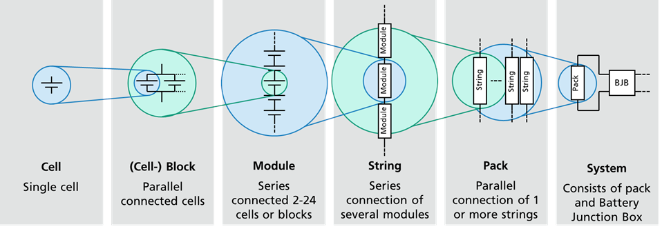
Naming conventions for battery system elements (as defined by the foxBMS project)#
A battery cell or cell is the smallest unit in a battery system. It has one positive terminal and one negative terminal.
Battery cells are usually connected in parallel to enhance the current capability of the system.
Battery cells connected in parallel form a (cell-)block.
Cells or cell blocks put in series form a battery module.
Several modules connected in series form a string.
Several strings connected in parallel form a battery pack.
The highest unit is the battery system. It is formed by the conjunction of a battery pack and a battery junction box (BJB). The BJB contains the elements used to control the current flow like power contactors and fuses.
Battery System Generation#
The battery systems are generated based on the requirements definition and the
battery cells that are available for this task.
To do this calculation, the BaSD tool uses a knowledge base containing the
information of how much overhead a typical system design the e.g., a liquid
cooled battery system consisting of cylindrical cells creates.
The BaSD tool then generates a report with the battery system configurations
it has found.
This report then includes the configuration. e.g.,
10 cells in parallel per cell block
15 cells in series per module
5 modules in series per string
2 strings in parallel per pack
based on some cell.
Further the BaSD tool can create a CAD design of the system to get a first
impression how the system looks like.
Inputs#
As already stated, BaSD needs requirements the battery system needs to
fulfill (i.e., the requirements file) and a cells that can be used for the
simulation (i.e., the cell database).
Requirements#
Note
All requirements need to be defined in basic SI unit or units derived from
them without any prefixes (e.g., to define a voltage of 1000V use
the value 1000 instead of 1k)
Requirements are defined by a json file that is passed to BaSD as
argument.
The file needs to define the following aspects of the battery system:
system: General system requirements. All settings here are optional. The default values are described below.optimized_by: determines the overall optimization goal (eithervolumeorweight, default:volume)cooling: type of cooling that should be considered (one ofAIR,GLYCOL,REFRIGERANT, default:TODO)cell: consider only a reduced set of cells:manufacturer: only from this manufacturermodel: only these modelformat: only cells with the specified format
electrical: Key for all electrical requirements:energy: minimum energy content (inWh)voltage: voltage limits:minimum: minimum voltage (inV)maximum: maximum voltage (inV)nominal: (desired) nominal voltage (inV)
continuous maximum: continuous maximum requirements:charge: in charge direction:power: power (inW)
discharge: in discharge direction:power: power (inW)
maximum module voltage: maximum module voltage a module shall not exceed (inV)
slave: BMS Slave requirements:minimum: minimum number of cells per slaves (dimensionless)maximum: maximum number of cells per slaves (dimensionless)equal utilization: determines whether all slaves on a module shall be equally utilized (e.g., if a module uses two slaves, both slaves measure the same number of cells)
mechanical: mechanical requirements:weight: maximum weight of the system (inkg)width: maximum width of the system (inm)height: maximum height of the system (inm)length: maximum length of the system (inm)
An exemplary requirements file could look like this:
{
    "system": {
        "optimized_by": "volume",
        "only_best": true,
        "cooling": "AIR",
        "cell": {
            "manufacturer": "Virtual",
            "model": "",
            "format": ""
        }
    },
    "electrical": {
        "energy": 20000,
        "voltage": {
            "minimum": 200,
            "nominal": 300,
            "maximum": 420
        },
        "continuous maximum": {
            "charge": {
                "power": 3220
            },
            "discharge": {
                "power": 4000
            }
        },
        "maximum module voltage": 60,
        "slave": {
            "minimum": 10,
            "maximum": 12,
            "equal utilization": true
        }
    },
    "mechanical": {
        "weight": 20000,
        "width": 50,
        "height": 20,
        "length": 50
    }
}
Cell Database#
Note
All cell parameters need to be defined in basic SI unit or units derived
from them without any prefixes (e.g., to define a length of 1mm use
the value 0.001 instead of 1mm)
The BaSD tool needs cell to calculate battery systems.
These cells are defined in a human read- and editable database that consists of
json files.
The database is installed into the users home directory (dependent on the
operating system).
A battery cell needs to define the following aspects of the battery cell:
identification: unique identification of the cell battery cell:manufacturer: manufacturer of the battery cell (arbitrary string)model: model of the battery cell (arbitrary string)
basic: basic information on the battery cell (mechanical and electrical parameters)mechanics: mechanical parameters:weight: cell weight (inkg)format: cell format (Cylindrical,PrismaticorPouch)(optional)
standard: whether the cell format adheres to a known cell format standard (arbitrary string)dimensions: cell dimensions: -height: cell height (inm) -length: cell length (inm) -width: cell width (inm)
electrics: electrical parameters:energycontentnominal: nominal energy content (inWh)minimum: minimum energy content (inWh)
voltage: cell voltagenominal: nominal cell voltage (inV)maximum: maximum cell voltage (inV)minimum: minimum cell voltage (inV)
current: current limitscharge: current limit in charge direction (inA)discharge: current limit in discharge direction (inA)
capacity: battery capacityinitial: battery capacity at the BOL (inAh)
discharge curve: a list of voltages reflecting the discharge curve from 100% SOC to 0%.
An exemplary cell file could look like this:
Warning
The OCV curve is shortened for simplify the introduction. A real cell the OCV curve actually needs a list with 101 entries (for every SOC point from 0% to 100% SOC).